
Direct answer: calculate the heat required by the product, divide by the verified useful heat released per kilogram of steam and the end-use efficiency, then add separately calculated warm-up and loss loads. Combine all users by time and pressure level. Size neither the boiler nor the pipe from the continuous product load alone.
Who uses this planning method?
Food process engineers
Develop heating duties for cookers, blanchers, smokehouses, kettles and heat exchangers.
Factory utility teams
Build pressure-level balances, distribution plans and condensate-return systems.
Equipment buyers
Give suppliers a consistent steam condition and operating profile for quotations.
Energy and commissioning teams
Measure real steam use, losses, warm-up and condensate recovery against production.
The formulas used by the estimator
Product heat duty (kW) = product flow (kg/h) x specific heat (kJ/kg.K) x temperature rise (K) / 3,600Continuous steam (kg/h) = heat duty x 3,600 / heat-transfer efficiency / useful steam heat (kJ/kg)Preliminary design steam (kg/h) = continuous steam x (1 + utility design allowance)The equation estimates sensible heating of a continuous product stream with a constant specific heat. It does not automatically include phase change, evaporation, frozen-product thawing, exothermic or endothermic reactions, vessel warm-up, water additions or distribution losses.
Worked example using the tool defaults
Heat 1,000 kg/h of product from 20 C to 85 C. Use specific heat 3.6 kJ/kg.K, 70% overall heat-transfer efficiency, 2,100 kJ/kg useful steam heat and 20% design allowance.
- Temperature rise = 65 K.
- Product heat duty = 1,000 x 3.6 x 65 / 3,600 = 65 kW.
- Continuous steam = 65 x 3,600 / 0.70 / 2,100 = 159 kg/h.
- Preliminary design steam = 159 x 1.20 = 191 kg/h.
The 191 kg/h result is one end-use estimate. It is not the boiler rating and does not prove pipe, valve or trap capacity.
Define every input from evidence
| Input | Engineering basis | Common error |
|---|---|---|
| Product flow | Maximum sustained mass flow in the heating step, including relevant recipe liquids. | Using saleable output after downstream losses. |
| Inlet temperature | Lowest credible product temperature during the design case. | Using room temperature for chilled or frozen ingredients. |
| Target temperature | Required bulk or outlet condition, separate from validated lethality. | Assuming one measured point represents the entire product. |
| Specific heat | Product formulation and temperature range from approved data or measurement. | Using water's value for every food. |
| Heat-transfer efficiency | Defined boundary covering the intended equipment losses and operating condition. | Adding the same loss again elsewhere. |
| Useful steam heat | Enthalpy decrease from actual inlet steam to defined outlet condensate/discharge. | Using a generic latent-heat value without pressure or condensate condition. |
| Allowance | Named uncertainty or reserve not already included in the other inputs. | Using allowance as a substitute for warm-up and concurrent-user calculations. |
Useful steam heat is an interface condition
Steam pressure determines saturation temperature and thermodynamic properties. The usable energy depends on steam dryness or superheat where relevant, pressure at the equipment while flowing, and the condensate condition leaving the heat exchanger. Obtain values from approved steam-property data for the project units and basis.
Useful heat per kg = inlet steam enthalpy - outlet condensate or discharge enthalpyDo not subtract returned-condensate energy from the end-use duty. Condensate return reduces boiler-house fuel and makeup-water requirements; it does not remove the heat already delivered to the process.
Continuous, batch and startup loads
A continuous product load can be relatively steady. A batch kettle or smokehouse instead has a heating cycle with a high initial rate, hold period and low-load stages. Vessel steel, internal water, racks, trolleys and piping all store heat during startup.
Warm-up energy (kJ) = sum of component mass x component specific heat x temperature riseAverage warm-up steam rate = warm-up energy / warm-up time / useful steam heatUse a time-step profile where several batches overlap. Boiler capacity may be controlled by the maximum coincident ramp, while annual energy is controlled by total cycle energy.
Four parts of the steam system
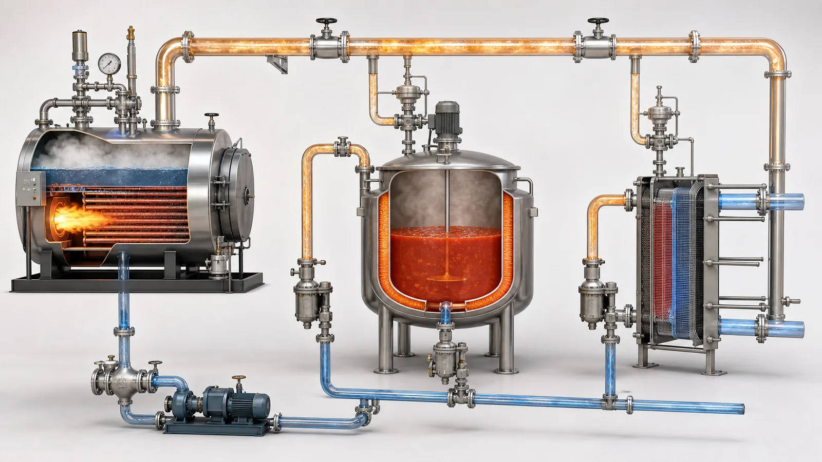
The U.S. Department of Energy's steam-system sourcebook organizes the system into generation, distribution, end use and recovery. Use the same boundaries in the project balance:
Generation
Fuel, boiler efficiency, feedwater, deaeration, blowdown, emissions, turndown and reserve.
Distribution
Headers, pressure reduction, insulation, separators, drip legs, traps, expansion and losses.
End use
Heat exchanger, control valve, steam condition, process duty, venting and operating profile.
Recovery
Condensate, flash steam, return pressure, contamination risk, receiver, pumping and heat recovery.
Indirect heating interface
For jackets, coils and heat exchangers, specify steam pressure and permitted variation at the equipment, maximum and normal mass flow, control-valve duty, connection, isolation, strainer, separator where required, trap arrangement, backpressure and condensate return condition. The equipment supplier and steam-system designer must agree who provides each item.
Heat-exchanger performance also depends on product viscosity, fouling, agitation, surface area and condensate removal. A correct energy balance cannot compensate for flooded heat-transfer surface or inadequate control-valve range.
Direct steam injection or infusion
Direct steam becomes part of the food. The calculation must therefore include both energy and mass:
- Added condensate changes total product mass, solids concentration and moisture.
- Steam-contact materials and boiler-water treatment require food-contact review for each market.
- Non-condensable gas, droplets and contaminants can affect heating and product quality.
- Downstream flash cooling or vacuum may remove some added water and needs its own balance.
- The validated process must confirm mixing, temperature distribution and required treatment.
Condensate and flash-steam planning
Record normal and peak condensate flow, pressure, temperature, contamination risk and return route. High-pressure condensate can flash when pressure falls. The return system must handle two-phase flow where it occurs and avoid excessive backpressure at steam traps.
Sample or monitor condensate where product leakage could contaminate the boiler system. Define when condensate is returned, diverted or discharged. Include receiver venting, pumping, heat recovery, water hammer prevention and safe drain locations.
From end-use demand to boiler capacity
Create a time-coincident load schedule for every pressure level:
- Continuous processing users at sustained maximum throughput.
- Batch heat-up profiles and permitted start sequence.
- Hot-water generation and sanitation demand.
- Smokehouse, blancher, cooker and CIP overlap.
- Header, pressure-reduction and distribution losses.
- Boiler blowdown, deaerator and feedwater conditions.
- Installed standby philosophy, future load and minimum stable turndown.
Boiler output rating, fuel input and steam condition are different quantities. Confirm rating basis, ambient/altitude corrections, feedwater temperature, emissions, local inspection and operator requirements with qualified boiler specialists.
Pressure safety and statutory scope
Boilers, receivers, pressure vessels, pressure piping, relief systems and their operation are regulated. ASME describes the Boiler and Pressure Vessel Code as a major technical source for boiler and pressure-vessel construction; the current ASME portal lists the 2025 BPVC. Adoption and required edition vary by jurisdiction. Other countries may use the EU Pressure Equipment Directive or national systems.
The process estimate does not design pressure equipment. Establish design pressure and temperature, materials, corrosion allowance, relief cases, inspection, welding, certification, registration and in-service examination under the legally applicable framework.
Metering and performance reconciliation
Choose a meter and installation suited to steam pressure, flow range, dryness and turndown. Retain pressure and temperature with mass-flow data. Reconcile steam against accepted production and operating state:
Specific steam use = measured steam mass / accepted product massCondensate return ratio = returned condensate mass / generated steam massDefine both numerator boundaries. A plant meter that includes hot-water generation cannot be compared directly with a single machine's product heating estimate.
Ten-step steam planning workflow
- Define products and cycles. Flow, recipe, inlet/target conditions, batches and schedules.
- Calculate product heat duty. Include phase changes and water additions where applicable.
- Calculate equipment warm-up. Metal, water, racks, pipe and allowed heat-up time.
- Set the steam condition. Pressure, quality and useful enthalpy at each end use.
- Develop time profiles. Continuous, batch, cleaning, startup and shutdown.
- Combine simultaneous users. Preserve pressure levels and start sequences.
- Design distribution and recovery. Include losses, trapping, flash and condensate return.
- Check boiler-house conditions. Feedwater, turndown, reserve, fuel, emissions and statutory scope.
- Freeze responsibility boundaries. Valves, separators, traps, metering and final connections.
- Commission and benchmark. Measure conditions, steam mass, production and condensate return.
Commissioning evidence
- Steam pressure and temperature at each equipment inlet during peak flow.
- Mass-flow profile through warm-up, steady production, hold and cleaning.
- Control-valve position and ability to maintain the required process condition.
- Trap operation, condensate backpressure, drainage and water-hammer observations.
- Product inlet/outlet flow and temperature under the agreed test recipe.
- Direct-injection product mass and moisture balance where applicable.
- Condensate return flow, temperature and contamination-control response.
- Boiler firing, header pressure and other users during the test.
- Safety-device, alarm, shutdown and loss-of-steam response records.
Steam demand planning FAQ
How do I estimate steam consumption for heating food?
Multiply product mass flow by specific heat and temperature rise, divide by heat-transfer efficiency and useful steam heat, then add separately calculated warm-up and system loads.
Is this the required boiler capacity?
No. Boiler capacity depends on time-coincident users, warm-up, pressure levels, losses, condensate/feedwater conditions, turndown, reserve and statutory requirements.
What is useful steam heat?
It is the enthalpy decrease from the actual inlet steam condition to the defined outlet condensate or discharge condition. Confirm it from approved steam-property data.
Can the estimator calculate direct injection?
It can screen heat demand, but direct injection adds water to the food. Complete a product mass, solids and moisture balance and confirm food-contact steam requirements.
Should the allowance include warm-up?
Preferably no. Calculate known warm-up energy and timing explicitly. Use allowance only for named uncertainty that is not already counted.
Primary references
- U.S. Department of Energy, Improving Steam System Performance: A Sourcebook for Industry.
- ASME Boiler and Pressure Vessel Code portal, including the 2025 BPVC resources.
- Electronic Code of Federal Regulations, 21 CFR 173.310, Boiler water additives.
- Codex Alimentarius, General Principles of Food Hygiene, CXC 1-1969.
Research reviewed: August 7, 2026. Planned review: August 7, 2027, or earlier if standards, equipment conditions or the steam-system basis changes.