
Direct answer: define every utility at the machine connection point, not only at the plant room. Record normal, peak and startup demand; required quality; pressure, temperature or voltage with permitted variation; connection and location; return or discharge; operating schedule; supplier/customer boundary; and verification method. Then combine equipment profiles by operating scenario instead of adding all nameplates blindly.
Who needs a utility interface schedule?
Food factory owners
Confirm that an existing site can support new processing capacity without hidden infrastructure work.
Machinery suppliers
Select motors, heaters, valves, heat exchangers, controls and connection hardware correctly.
MEP and process engineers
Size distribution systems from realistic simultaneous demand and quality at point of use.
Commissioning teams
Test agreed conditions at the interface and separate machine faults from utility shortfalls.
Checklist, schedule and balance are different
| Document | Question answered | Project use |
|---|---|---|
| Availability checklist | Does the site have electricity, water, drainage, steam, air, refrigeration and exhaust? | Early enquiry and missing-information review. |
| Equipment utility schedule | What does each machine require at its connection point? | Quotation, layout, interfaces and procurement. |
| Plant utility balance | What is the combined demand under each operating scenario? | Generation, distribution, storage and capacity design. |
| Acceptance record | What was measured at commissioning and did it pass? | Release, troubleshooting and baseline control. |
The online checklist creates the first document. This guide explains the additional engineering required before order release and installation.
Minimum fields for every connection
| Field | What to record | Why it matters |
|---|---|---|
| Utility and service | Electricity, potable water, process water, steam, air, refrigerant, exhaust, drain or other service. | One utility may serve several risk classes and conditions. |
| Demand profile | Standby, normal, peak, startup, cleaning and duration. | A single average cannot size a peak-sensitive system. |
| Required condition | Voltage/frequency, pressure, temperature, flow, quality and allowed variation. | Nameplate values without tolerances are not an interface. |
| Connection | Size, type, material, orientation, elevation and drawing reference. | Prevents field adapters and inaccessible isolation points. |
| Return or discharge | Condensate, warm water, wastewater, heat, air or refrigerant return conditions. | The outgoing side can control system capacity and hygiene. |
| Boundary | Who supplies isolation, regulation, filtration, metering, flexible connection and final hookup. | Closes scope gaps between machine and building contractors. |
| Acceptance | Instrument, point, operating state, duration and pass criteria. | Makes commissioning objective and repeatable. |
Demand is a time profile, not one number
Connected load = sum of installed equipment nameplate loadsScenario demand = sum of equipment loads operating simultaneously in that scenarioPeak demand = highest time-coincident scenario demand, including relevant startup or cleaning eventsDesign capacity = verified peak demand + justified reserve, corrected for distribution losses and required conditions at point of useDevelop scenarios for normal production, simultaneous heat-up, product change, sanitation, defrost, shift startup, shutdown and credible equipment overlap. Do not apply one diversity factor to electricity, steam, water and compressed air; their timing and storage behaviour differ.
Example: why simultaneous operation must be defined
Three machines each show 60 kW connected load. During steady production they draw 42, 35 and 18 kW, but only the first two heat simultaneously. A wash system adds a separate 45 kW load when production is stopped.
- Connected total = 180 kW, or 225 kW if the wash system is included.
- Steady production demand = 95 kW.
- Production startup must be checked from the actual heat and motor sequence, not assumed to be 180 kW.
- Sanitation demand is 45 kW plus services intentionally operating during cleaning, not automatically added to full production.
The project schedule must preserve these operating assumptions. If the plant later changes sequencing, capacity must be reviewed.
Electrical supply interface
Record country and project standard, nominal voltage, frequency, phases, grounding arrangement, permitted variation, available fault level, protective device coordination and environmental conditions. For each machine include connected and operating power, full-load current, largest motor, starting method, heater staging, power factor, harmonic-producing loads, control supply and emergency-stop interfaces.
IEC 60204-1:2016 with Amendment 1:2021 is the valid consolidated edition listed by IEC at the review date. Its machine electrical scope starts at the point where the supply connects to the machine electrical equipment. The project must explicitly define the installation upstream of that point and the final field connection.
Water supply and cleaning demand
Separate potable ingredient water, product-contact process water, non-contact cooling water, cleaning water, hot water and treated water. For each service define use, source, quality at point of use, normal and instantaneous flow, pressure, temperature, operating duration, backflow protection, treatment, storage and monitoring.
- Ingredient and direct-contact water require a risk-based quality specification for the intended food and market.
- Cleaning demand is often intermittent and can create the plant's largest short flow peak.
- Heat-exchanger cooling circuits require supply and return temperatures, flow, pressure drop and water quality.
- Hose stations must be included in simultaneous cleaning scenarios rather than hidden in an average daily volume.
- Returned or reused water needs a defined risk assessment, treatment and segregation strategy.
Drainage and wastewater interface
Drainage is an engineered utility, not an empty box below a machine. Record gravity or pumped discharge, peak and batch volume, temperature, pH range, fats, solids, salinity, cleaning chemicals, product load and discharge timing. Identify screens, traps, separation, equalization or pretreatment and who supplies them.
Codex CXC 1-1969 states that drainage and waste-disposal systems should avoid contaminating food or the water supply. Layout must prevent less-clean drainage from creating risk in cleaner areas. Final design also requires local sewer, environmental and plumbing requirements.
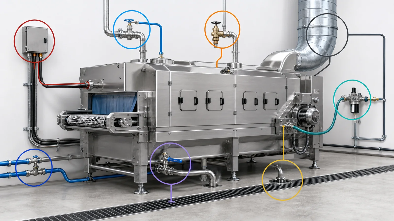
Steam and condensate
Define whether steam is indirect plant steam, clean steam or culinary/direct-contact steam according to the product and applicable rules. Record pressure and temperature at the connection, mass-flow profile, startup peak, permitted pressure variation, steam quality basis, boiler-treatment constraints, control-valve duty, condensate pressure and temperature, flash steam, return arrangement and drainage during shutdown.
A heat duty does not directly equal boiler capacity. Distribution warm-up, line loss, trap performance, condensate return, simultaneous users and the required pressure at the furthest machine must be evaluated by the utility designer.
Compressed air quality and demand
List every use: actuator, instrument, air knife, package inflation, product contact or cleaning. State pressure at the machine while flowing, normal and peak free-air demand, duty cycle, connection, dew point and contaminant limits appropriate to risk.
ISO 8573-1:2010 classifies compressed-air purity for particles, water and oil and identifies gaseous and microbiological contaminants. ISO lists the edition as published but under revision. A project should identify the exact edition, individual class limits, measurement parts and sampling location rather than writing only "ISO 8573" or "food grade air."
Refrigeration and product cooling
Separate product load, equipment heat, infiltration, people, lighting, defrost and pull-down. For a machine interface, specify cooling medium, supply and return temperatures, required flow, pressure, pressure drop, fouling basis, material compatibility, control method and allowable product-side conditions. For direct-expansion systems, define refrigerant, design conditions, pipe and control scope, oil return and safety responsibilities.
Plant capacity must be checked at the required evaporating and condensing conditions, not compared only by nominal compressor power or a catalogue refrigeration rating.
Exhaust, ventilation and heat rejection
Identify sensible heat, water vapour, grease, smoke, aerosols, odour and combustion products at source. Define capture method, exhaust flow and pressure, duct material and cleaning access, condensate drainage, make-up air, discharge location and room-pressure intent. Coordinate hoods with equipment opening, cleaning and maintenance envelopes.
Air balance must support the hygiene zoning strategy. More exhaust without controlled replacement air can pull contamination through doors and openings or cause condensation and unstable hoods.
Space, access and civil interfaces
The checklist also asks for production space and floor/access limits because utilities cannot be coordinated independently of layout. Record room length, width and clear height, columns, floor load, pits, drains, doors, lifting routes, forklift envelope, equipment delivery path, panel clearance and major component removal.
Responsibility boundary matrix
| Interface item | Machine supplier | Factory or contractor | Must be frozen by |
|---|---|---|---|
| Machine internal distribution | Design, component selection and internal testing. | Provide approved incoming condition. | Machine design release. |
| Isolation and final connection | State connection and access requirements. | Supply/install unless contract says otherwise. | Installation drawing approval. |
| Conditioning equipment | State required point-of-use quality. | Provide plant or local filtration, regulation and treatment as allocated. | Utility design freeze. |
| Metering and acceptance | Define machine test state and data needed. | Provide calibrated measurement where allocated. | Commissioning plan approval. |
| Return/discharge | State outlet condition and limits. | Receive, treat and dispose or return safely. | Civil/MEP coordination. |
Ten-step utility planning workflow
- Record the site basis. Country, standards, environment, operating schedule and existing services.
- Create one line per machine connection. Do not combine unrelated uses under one utility name.
- Define point-of-use conditions. Include allowed ranges and quality, not only nominal values.
- Build time profiles. Normal, peak, startup, cleaning, defrost and standby.
- Develop operating scenarios. State which equipment runs together and for how long.
- Calculate plant balances. Include distribution losses and justified reserve separately.
- Freeze connection locations. Coordinate layout, hygiene, access, slopes and maintenance.
- Allocate responsibility. Close every gap from plant distribution to machine internals and back.
- Prepare acceptance tests. Define instruments, sampling points, operating state and pass criteria.
- Control changes. Recalculate balances when products, speeds, equipment or schedules change.
Commissioning evidence
- As-built connection size, material, location, identification and flow direction.
- Voltage, frequency, phase balance and relevant electrical protection data under load.
- Pressure, temperature and flow at the machine during the agreed peak scenario.
- Water and compressed-air quality results from the specified sampling points and methods.
- Steam and condensate conditions during startup and stable operation.
- Drain performance during maximum credible simultaneous discharge.
- Refrigeration supply/return conditions and product response at representative load.
- Exhaust capture, make-up air and room-pressure behaviour with doors in agreed states.
- Alarm, isolation, emergency shutdown and loss-of-utility recovery tests.

Food factory utility planning FAQ
What utility information does a machinery supplier need?
Provide service purpose, normal and peak demand, point-of-use quality and conditions, allowed variation, connection and location, return or discharge, operating schedule, responsibility boundary and acceptance method.
Can machinery be quoted before utilities are final?
A preliminary quotation can use documented assumptions. Final motors, heaters, controls, valves, heat exchangers, refrigeration and installation scope require approved utility data.
Why are connected load and peak demand different?
Connected load adds nameplates. Peak demand depends on which loads operate together over time. Startup, heat-up, cleaning and defrost can create peaks outside normal production.
Is food-grade compressed air a complete specification?
No. Define contaminant limits, measurement methods, sampling point, pressure and demand from the product-contact risk assessment. Cite the exact ISO 8573 edition and relevant parts where used.
Should drainage appear on the machine utility schedule?
Yes. Record flow profile, temperature, chemistry, solids, connection, discharge method and pretreatment responsibility. Drainage capacity and location affect hygiene and layout.
Primary references
- IEC 60204-1:2016, Safety of machinery - Electrical equipment of machines - Part 1; IEC also lists Amendment 1:2021 as valid.
- ISO 8573-1:2010, Compressed air - Part 1: Contaminants and purity classes, published and under revision as of the review date.
- Codex Alimentarius, General Principles of Food Hygiene, CXC 1-1969, revised 2022 publication.
- Electronic Code of Federal Regulations, 21 CFR 117.37, Sanitary facilities and controls.
Research reviewed: August 7, 2026. Planned review: August 7, 2027, or earlier if standards, equipment scope or site conditions change.