
Direct answer: create a load register for every machine and auxiliary system, distinguish electrical input from motor output, and group loads by operating scenario. Calculate real power, apparent power and current at the approved voltage and power factor. Then separately check motor starting, heater steps, VFD harmonics, short-circuit duty, protective coordination, cable derating, voltage drop, environmental protection and emergency-power scope.
Who uses this planning method?
Factory owners
Screen whether the incoming service, transformer and existing distribution have enough project capacity.
Process and project engineers
Build realistic operating scenarios from machine sequences, heat-up, sanitation and refrigeration.
Electrical designers
Use approved machine data as the input to protection, cable, panel, transformer and power-quality design.
Commissioning teams
Compare measured voltage, current, demand and energy with the released operating basis.
Understand the four quantities
| Quantity | Meaning | Do not use it as |
|---|---|---|
| kW | Real electrical power converted into useful work and losses. | Apparent supply capacity without considering power factor. |
| kVA | Apparent power used when considering source and distribution capacity. | Energy consumption or utility bill kWh. |
| A | Current under stated voltage, phase, power factor and operating conditions. | Automatic cable or breaker selection. |
| kWh | Electrical energy accumulated over operating time. | Instantaneous peak-demand capacity. |
The formulas used by the online estimator
Running demand (kW) = connected load (kW) x simultaneous demand factorPreliminary design demand (kW) = running demand x (1 + capacity reserve)Design apparent power (kVA) = preliminary design demand / power factorThree-phase current (A) = kVA x 1,000 / (sqrt(3) x line-to-line voltage)Daily energy (kWh/day) = running demand x operating hours/dayThe formula assumes a balanced three-phase planning load and one aggregate power factor. It does not model equipment efficiency, single-phase distribution, neutral harmonic current, regenerative loads, motor starting or power-factor variation. The reserve is applied to design demand and kVA, but not to the displayed daily energy.
Worked example using the estimator defaults
Assume 180 kW total connected equipment input, 75% simultaneous demand, 0.85 power factor, 400 V three-phase supply, 8 operating hours/day and 20% capacity reserve.
- Running demand = 180 x 0.75 = 135 kW.
- Preliminary design demand = 135 x 1.20 = 162 kW.
- Apparent power = 162 / 0.85 = 190.6 kVA.
- Estimated line current = 190.6 x 1,000 / (1.732 x 400) = 275 A.
- Daily energy = 135 x 8 = 1,080 kWh/day.
These values frame an enquiry. They do not select a standard transformer, feeder, breaker or generator.
Build a controlled electrical load register
| Field | Minimum content | Reason |
|---|---|---|
| Equipment and load ID | Machine, motor, heater, refrigeration, control, socket or auxiliary function. | Maintains traceability to layout and single-line diagram. |
| Supply | Voltage, frequency, phase, grounding arrangement and allowed variation. | Prevents incompatible motors, heaters and controls. |
| Input rating | Electrical kW/kVA, rated current and supplier basis. | A motor's shaft kW may not equal electrical input. |
| Load type | Motor, resistive heater, transformer, VFD, electronic supply or mixed machine. | Influences starting, power factor and harmonics. |
| Operating state | Standby, normal, maximum, startup, heat-up, cleaning and duration. | Supports time-coincident demand scenarios. |
| Starting/control method | Direct-on-line, star-delta, soft starter, VFD or staged heater. | Defines transient demand and process behaviour. |
| Criticality | Normal, essential, life safety, controlled shutdown or restart prohibited. | Supports backup and load-shedding design. |
| Data status | Budget, vendor estimate, approved submittal, nameplate or measured. | Shows uncertainty and when recalculation is required. |
Connected load is not simultaneous demand
Develop scenarios from the process sequence rather than applying one unsupported percentage to the whole factory. Include normal production, line startup, simultaneous heat-up, refrigeration pull-down, defrost, sanitation, maintenance, shift change and restart after a power interruption.
- Motors may cycle or modulate instead of operating continuously at full input.
- Electric heaters can be staged, modulated or fully energized during heat-up.
- Compressors and refrigeration systems respond to product and ambient load.
- Cleaning equipment may operate when production loads are off, or may overlap during phased sanitation.
- Conveyors that normally run together should not receive independent diversity without evidence.
Motor starting and voltage performance
Record motor rated current, locked-rotor or starting data, load torque, acceleration time, starts per hour and starting method. Check voltage dip at the motor and upstream buses, contactor and protection behaviour, generator capability and interaction with other operating equipment. A VFD can reduce starting current but adds power-electronic and motor-application considerations.
Heaters, controls and auxiliary loads
Separate heaters from motors because heater demand, switching and phase balance differ. Include cabinet cooling, control transformers, PLCs, HMIs, safety systems, instrumentation, trace heating, sump heaters, lighting, extraction fans, pumps and local service outlets. State whether machine ratings include every supplied auxiliary panel and skid.
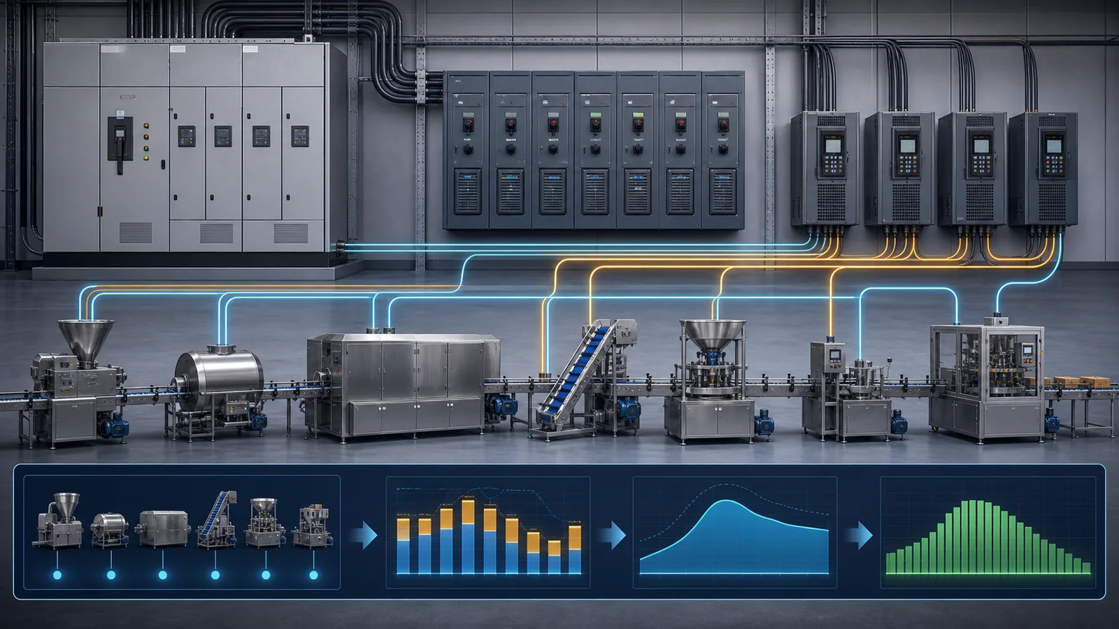
VFDs, harmonics and power factor
Variable-frequency drives can improve process control and reduce energy on suitable variable-torque loads, but the electrical design must consider harmonic currents, electromagnetic compatibility, cable length, motor insulation, bearing currents, switching frequency and heat rejection. U.S. Department of Energy guidance notes that VFDs can be significant harmonic sources and that capacitor correction can interact with system resonance.
Do not assume one nameplate power factor represents the plant at every load. Obtain supplier input-current and harmonic data for significant nonlinear loads and perform the study required by the local design basis.
From estimated current to feeder design
IEC 60364-5-52 addresses selection and erection of wiring systems, including current capacity, harmonic-current considerations, voltage drop, connections and maintainability. The valid consolidated edition listed by IEC at the review date is IEC 60364-5-52:2009 with Amendment 1:2024. Applicable national codes may differ or add requirements.
A qualified design must check at least:
- Installation method, conductor material, insulation and termination temperature ratings.
- Ambient temperature, grouping, thermal insulation, wet conditions and washdown environment.
- Continuous and cyclic loading, harmonics, neutral current and phase balance.
- Normal and starting voltage drop at the machine terminals.
- Overload and short-circuit protection, disconnection times and selectivity.
- Available fault current versus equipment interrupting and short-circuit ratings.
- Protective bonding, earthing, residual-current protection and local isolation.
- Arc-flash and electrical-work requirements where applicable.
Machine and building responsibility boundary
IEC 60204-1:2016 applies to machine electrical equipment beginning at the point where the supply connects to the machine. IEC lists Amendment 1:2021 with the base publication as a valid consolidated edition. In North American projects, NFPA 79:2024 addresses industrial machinery electrical equipment, while the adopted edition of NFPA 70 and local amendments govern the installation.
Freeze the supply connection, disconnect, overcurrent protection, fault-current data, cable entry, neutral, protective conductor, field wiring, interlocks, emergency-stop links and testing responsibility in a matrix. Do not assume the machinery supplier provides the upstream feeder or that the electrical contractor provides machine-internal protection.
Transformer and generator planning
Transformer selection needs more than the calculated kVA: ambient and installation conditions, impedance, voltage regulation, harmonics, load growth, losses, fault level, inrush, redundancy and maintainability can control. Generator and UPS scope must be based on an essential-load list and transition sequence, not the entire connected factory load by default.
Classify what must run through a short interruption, what may restart automatically, what requires product-safe shutdown and what must not restart without inspection. Include controls, valves, pumps, refrigeration, alarms, data systems and safe egress, not only main drive motors.
Energy planning is separate from capacity planning
The estimator's daily kWh assumes constant average demand for the entered hours. A stronger forecast uses a time profile by product, shift, cleaning cycle, ambient condition and idle state. Compare meter data with accepted production to calculate kWh per tonne or per thousand packs, while retaining product mix and quality context.
A machine with lower peak kW can still consume more kWh if it runs longer. Conversely, a high-power heater can create a short capacity peak without dominating monthly energy.
Ten-step electrical planning workflow
- Freeze the electrical basis. Country, adopted standards, voltage, frequency, phases, grounding and environment.
- Create the load register. Include supplied and site-provided auxiliaries.
- Verify electrical input data. Do not substitute motor output ratings.
- Build operating scenarios. Normal, startup, heat-up, sanitation, defrost and recovery.
- Calculate kW, kVA and current. State power factor and uncertainty.
- Study transients and power quality. Starting, voltage dip, harmonics and phase balance.
- Coordinate source and distribution. Transformer, generator, panels, feeders and local isolation.
- Complete protection studies. Fault current, ratings, coordination, grounding and applicable safety analysis.
- Freeze interface drawings. Connection point, cable route, entry, environment and responsibilities.
- Commission and update. Replace assumptions with approved and measured data.
Commissioning evidence to retain
- As-built single-line diagram, load register and protective-device settings.
- Machine nameplates, approved electrical drawings and short-circuit ratings.
- Supply voltage, frequency, phase sequence and phase balance before connection.
- Protective-conductor and bonding verification required by the project standard.
- Running and peak current by phase during agreed process scenarios.
- Voltage at the machine during the largest relevant start or heater step.
- Power factor, harmonics or power-quality records where the design requires them.
- Emergency stop, isolation, loss-of-power and restart-sequence test results.
- Baseline kW and kWh linked to product, throughput and operating time.

Electrical load planning FAQ
What is connected electrical load?
It is the sum of applicable electrical input ratings for installed equipment. It is not necessarily simultaneous demand, and motor shaft-output kW should not be used as electrical input without efficiency and supplier data.
How do I estimate three-phase current from kW?
For a balanced preliminary estimate, divide kW times 1,000 by square root of three, line voltage and power factor. The Helper tool applies demand and reserve before this calculation.
Can the estimated current select a cable or breaker?
No. Selection also needs adopted code, installation and ambient derating, voltage drop, starting, harmonics, fault level, protective coordination, conductor and terminal data.
Should capacity reserve be included in daily kWh?
No. Reserve is spare design capacity, not expected consumption. The tool calculates daily energy from running demand before reserve.
Can I use one demand factor for the whole line?
Only as an early documented assumption. Final demand should come from actual sequences and time-coincident load scenarios.
Primary references
- IEC 60204-1:2016, Safety of machinery - Electrical equipment of machines - Part 1, with Amendment 1:2021 listed by IEC.
- IEC 60364-5-52:2009, Low-voltage electrical installations - Wiring systems, with Amendment 1:2024 consolidated edition listed by IEC.
- NFPA 79:2024, Electrical Standard for Industrial Machinery.
- NFPA LiNK publications list, including the 2026 edition of NFPA 70.
- U.S. Department of Energy, Motor Systems technical resources.
Research reviewed: August 7, 2026. Planned review: August 7, 2027, or earlier if standards, equipment data or the site electrical basis changes.