
Direct answer: calculate average free-air demand from each device's free air per cycle and actual cycle profile. Keep leakage and growth separate, then build a time-coincident load schedule. Confirm the minimum flowing pressure and contaminant limits at each point of use. Size compressors, dryers, filters, receivers and pipework from peak behaviour, ambient conditions, control strategy, pressure drop and redundancy, not average litres per minute alone.
Who uses this planning method?
Food factory engineers
Develop compressor, treatment, storage and distribution requirements for new or expanded lines.
Machinery suppliers
State free-air demand, minimum pressure, connection and quality at the machine interface.
Food-safety and quality teams
Classify product-contact risk and establish monitoring and response requirements.
Maintenance and energy teams
Control pressure, leaks, inappropriate uses and specific energy over the system life.
The formulas used by the online estimator
Average process demand (L/min free air) = litres/cycle x cycles/min x machine count x simultaneous active dutyPreliminary design demand = average process demand x (1 + leakage and design allowance)Hourly free-air volume (m3/h) = design L/min x 60 / 1,000Daily free-air volume (m3/day) = hourly volume x operating hours/dayThe input is free air per cycle, not compressed cylinder volume. The formula averages cyclic use over a minute and therefore does not show the instantaneous flow through valves, tubing and regulators.
Worked example using the estimator defaults
Two identical machines consume 4.5 L free air/cycle at 20 cycles/min. Use 80% simultaneous active duty, 25% combined leakage/design allowance and 8 hours/day.
- Average process demand = 4.5 x 20 x 2 x 0.80 = 144 L/min.
- Preliminary design demand = 144 x 1.25 = 180 L/min.
- Equivalent design flow = 0.180 m3/min or 10.8 m3/h.
- Daily volume = 10.8 x 8 = 86.4 m3/day.
This does not prove that the machines will maintain pressure when both actuate at the same instant.
Build one demand line for each use
| Field | Minimum content | Why it matters |
|---|---|---|
| Use and device | Cylinder, valve, clipper, air knife, package inflation, conveying, instrument or cleaning. | Different uses have different peak and purity risks. |
| Free air per event | Supplier value with reference conditions and complete stroke/event definition. | Prevents mixing compressed and free-air volumes. |
| Frequency and duty | Events/minute, event duration, machine count and simultaneous sequence. | Defines average and peak flow. |
| Pressure | Minimum and maximum at the machine while flowing, plus permitted variation. | Static header pressure does not prove actuator performance. |
| Purity | Contaminants, limits, test methods and sampling point. | "Clean" or "food grade" is not measurable. |
| Connection | Size, type, regulator, isolation, hose/tube and location. | Local restrictions can cause the dominant pressure drop. |
| Operating state | Normal, startup, changeover, cleaning, upset and standby. | Supports time-coincident system scenarios. |
Free air, pressure and reference conditions
Compressor capacity is commonly stated as free-air delivery or a standardized inlet-referenced flow. Actual mass delivered changes with inlet pressure, temperature, humidity, altitude and compressor condition. Record the exact rating standard and reference conditions when comparing offers.
At the machine, state gauge pressure and the location where it must be maintained. Include pressure losses through the dryer, filters, main, drops, shutoff, regulator, soft-start valve, tubing and machine valve manifold. Raising compressor pressure to compensate for a local restriction wastes energy and increases leakage.
Average flow, instantaneous peak and receiver storage
A cylinder can consume its cycle volume in a fraction of a second. Tubing and valves must pass this local event, while a receiver can buffer demand above compressor supply. The U.S. Department of Energy sourcebook provides the following simplified storage relationship for an isothermal receiver with no compressor supply during the event:
Receiver volume = event time x free-air demand x absolute atmospheric pressure / (initial gauge pressure - final gauge pressure)Use consistent units. If the compressor supplies air during the event, use net demand above compressor delivery. Real design also needs temperature, control response, pressure losses, legal pressure-vessel requirements and receiver location.
Separate leakage from capacity reserve
The estimator combines leakage and design allowance in one input for early screening. A project schedule should separate them:
- Process demand: useful air required by the approved operating sequence.
- Measured leakage: non-productive flow when equipment should be idle.
- Temporary uncertainty: allowance while supplier data remains preliminary.
- Future capacity: named machines or production scenario with a target date.
Do not institutionalize a large leakage percentage as permanent compressor capacity. Provide isolation by area or machine, measure off-shift flow, tag leaks and verify repairs.
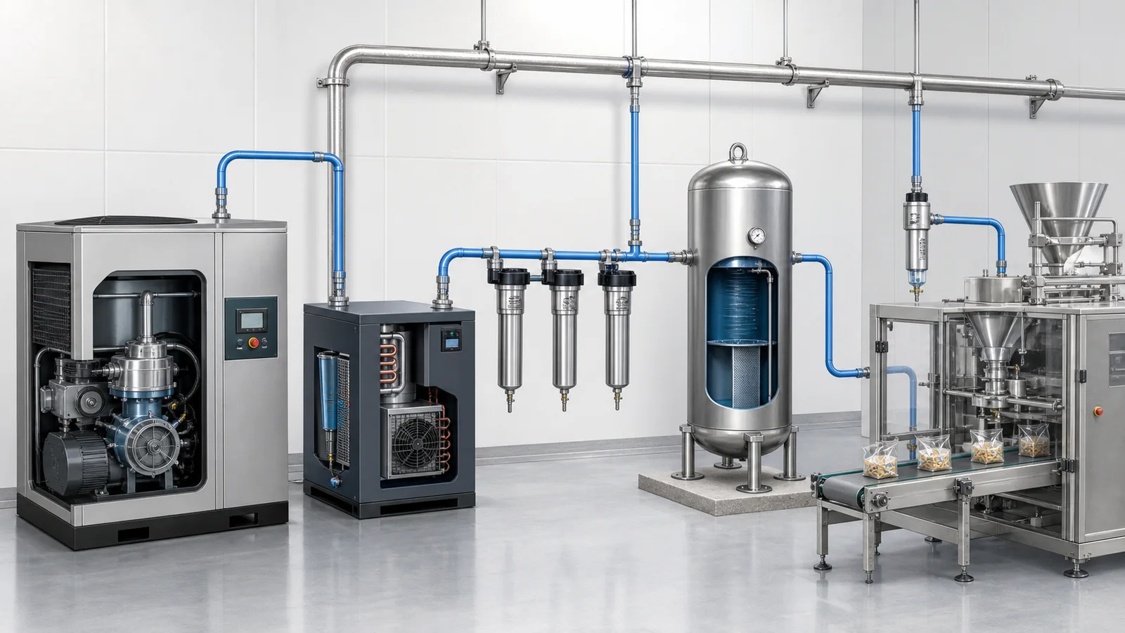
Air-quality zoning by use
| Use category | Risk question | Typical controls to evaluate |
|---|---|---|
| No product contact | Can exhaust, leakage or maintenance still reach exposed food or packaging? | Source location, exhaust route, oil/water carryover and local hygiene zone. |
| Indirect contact | Can air contact a product-contact surface, primary package interior or cleaning result? | Point-of-use treatment, materials, monitoring and shutdown response. |
| Direct product contact | Can contaminants enter food through blowing, aeration, conveying or package inflation? | Hazard-based particle, water, oil, gas and microbiological specification and validation. |
| Instrument/control air | Can quality or pressure failure create unsafe valve or process states? | Reliability, dew point, filtration, reserve and fail-safe position. |
Use ISO 8573 precisely
ISO 8573-1:2010 specifies compressed-air purity classes for particles, water and oil and identifies gaseous and microbiological contaminants. ISO lists the edition as published but under revision. It does not assign one universal food-industry class.
A complete requirement identifies the exact edition, each contaminant limit, relevant measurement part and sampling point. Examples in the series include ISO 8573-2:2018 for oil aerosol, ISO 8573-4:2019 for particle content, ISO 8573-5:2025 for oil vapour and ISO 8573-7:2003 for viable microbiological contaminant content. Check current status before project release.
Sampling downstream of treatment but far upstream of the machine may miss contamination, condensate or microbial growth in the distribution system. Define representative and worst-case points and the response to a failed result.
Compressor and dryer planning
Build a pressure-flow profile rather than matching one catalogue number. Evaluate compressor type, control range, minimum stable flow, loaded/unloaded power, number of units, standby philosophy, ambient and altitude correction, intake-air quality, ventilation, heat recovery, noise and maintenance access.
Select drying technology from the required pressure dew point at actual site conditions. Account for dryer purge or regeneration air, filter pressure drop over its service life, drains and bypass risk. Treatment capacity must match maximum inlet temperature, flow and pressure, not only average production demand.
Distribution and point-of-use design
- Use a hydraulic model for mains, branches, rings, long drops and simultaneous users.
- Slope and drain systems as required by the selected moisture-control strategy.
- Take branch air in a way that reduces liquid carryover where appropriate.
- Provide accessible isolation and identify quality zones and flow direction.
- Keep pipe material, corrosion, sealants and installation cleanliness consistent with purity needs.
- Size local regulators, valves, hoses and silencers for peak flow, not average L/min.
- Prevent dead legs or inaccessible sections where hygiene risk makes them unacceptable.
Safety and inappropriate uses
Air receivers are pressure vessels and require the applicable design, relief, inspection, drainage and operating controls. OSHA's U.S. general-industry information identifies pressure gauges, safety valves and removal of accumulated oil and water among receiver requirements; project rules depend on jurisdiction.
Compressed air can inject material into skin, propel particles and create high noise. Do not use it to clean people. Avoid open blowing where vacuum, a blower or engineered nozzle can perform the task with lower pressure and risk. OSHA guidance recommends minimum pressure needed, leak repair and shutting air off when equipment is idle.
Ten-step compressed-air planning workflow
- Classify every use. Function, contact risk, pressure and criticality.
- Collect free-air event data. Record reference conditions and supplier status.
- Build cycle profiles. Event duration, frequency, machine count and simultaneity.
- Calculate average demand. Keep process, leakage, uncertainty and growth separate.
- Model peak events. Include valves, tubing and acceptable pressure decay.
- Set purity requirements. Contaminants, limits, methods, points and response.
- Select generation and treatment. Correct for ambient, dryer purge and pressure loss.
- Model distribution. Prove minimum flowing pressure at the furthest critical user.
- Allocate interfaces and safety. Receiver, relief, drains, isolation and final connection.
- Commission and benchmark. Measure pressure, flow, quality, leakage and energy.
Commissioning evidence
- Compressor free-air delivery and power under agreed reference/site conditions.
- Header and point-of-use pressure during normal and worst simultaneous cycles.
- High-speed pressure trace for the controlling peak event.
- Dryer inlet/outlet conditions, pressure dew point and purge demand where applicable.
- Particle, water, oil and risk-based contaminant results at specified points.
- Filter differential pressure at clean and defined service conditions.
- Receiver identification, certification, relief, gauge and drain records.
- Off-shift leakage baseline and isolation-zone flow.
- Specific energy, compressor kWh per delivered standard volume, with stated boundaries.
- Loss-of-air, low-pressure alarm and machine fail-safe response.
Compressed air planning FAQ
How do I calculate demand for cyclic machinery?
Multiply free air per cycle by cycles per minute, machine quantity and simultaneous active duty. Add separately justified leakage and reserve, then check instantaneous peak flow and pressure.
What is free-air delivery?
It references compressor output to stated inlet or standard conditions rather than pressurized pipe volume. Compare suppliers only on the same reference basis.
Can average flow size a receiver?
No. Receiver size depends on net peak demand, duration, initial and minimum pressure, temperature assumptions and compressor control response.
What ISO class is required for food contact?
There is no universal class for every application. Set limits from a product and process risk assessment, cite the exact ISO 8573 edition and test parts, and define sampling points.
Should leakage be included in new compressor capacity?
Measure and repair it rather than treating a large leakage allowance as permanent useful demand. Keep leakage, uncertainty and future expansion as separate lines.

Primary references
- U.S. Department of Energy, Improving Compressed Air System Performance: A Sourcebook for Industry.
- ISO 8573-1:2010, Compressed air - Part 1: Contaminants and purity classes, published and under revision.
- ISO 8573-4:2019, Compressed air - Contaminant measurement - Particle content.
- Codex Alimentarius Codes of Practice, including CXC 1-1969, revised 2022.
- U.S. OSHA General Industry Digest, including air-receiver safety information.
Research reviewed: August 7, 2026. Planned review: August 7, 2027, or earlier if ISO 8573 status, equipment data or the site air-system basis changes.