
Direct answer
Do not size a food-factory supply by adding motor nameplate kW and applying one arbitrary percentage. Create an equipment load register, distinguish electrical input from shaft output, assign utilization and coincidence by operating scenario, convert real power to apparent power using verified power factor, and separately assess starting, harmonics, short circuit, safety services and future expansion. The resulting kW and kVA are preliminary design inputs, not final equipment ratings.
Connected load, demand and energy are not the same
Connected load, kW
The declared electrical input of all connected equipment. A motor plate may state shaft output, so obtain supplier input current, efficiency and power-factor data where necessary.
Operating demand, kW
The estimated real power used in a defined condition after applying equipment utilization and actual control behavior.
Apparent power, kVA
The supply and transformer planning quantity related to real power through power factor. Nonlinear loads require more analysis than one aggregate cosine value.
Energy, kWh
Power integrated over time. It supports operating-cost estimates but does not by itself define feeder, protection or transformer capacity.
Core electrical load formulas
estimated load kW = declared input kW x utilization factor x coincidence factorapparent power kVA = real power kW / power factorbalanced 3-phase current A = kVA x 1000 / (sqrt(3) x line-to-line volts)Use these only after defining the operating scenario. Final current, conductor and protection calculations must follow applicable codes and actual equipment data.A utilization factor describes how heavily an item operates relative to its declared input. A coincidence factor describes whether its maximum occurs at the same time as other loads. Schneider Electric's engineering guide notes that these factors require detailed knowledge of the installation and should not be treated as universal values.
Example: one production scenario at 400 V
This example demonstrates the method, not recommended factors. The project team must replace every assumption with equipment data and a production sequence.
| Load group | Input kW | Utilization | Coincidence | Scenario demand |
|---|---|---|---|---|
| Dough or meat mixing | 45.0 | 0.80 | 1.00 | 36.00 kW |
| Forming or sheeting | 30.0 | 0.75 | 1.00 | 22.50 kW |
| Conveyors | 18.0 | 0.65 | 0.90 | 10.53 kW |
| Allocated compressed-air plant | 55.0 | 0.85 | 0.80 | 37.40 kW |
| Process refrigeration | 90.0 | 0.75 | 0.80 | 54.00 kW |
| CIP and cleaning equipment | 24.0 | 0.70 | 0.50 | 8.40 kW |
| Controls, lighting and support | 20.0 | 0.90 | 1.00 | 18.00 kW |
| Total | 282.0 kW connected | Defined production case | 186.83 kW | |
preliminary kVA at PF 0.90 = 186.83 / 0.90 = 207.59 kVApreliminary current at 400 V = 207.59 x 1000 / (1.732 x 400) = 299.6 AThe scalar power factor and balanced-current result are screening assumptions. They do not account for phase imbalance, harmonics, motor start or code-required margins.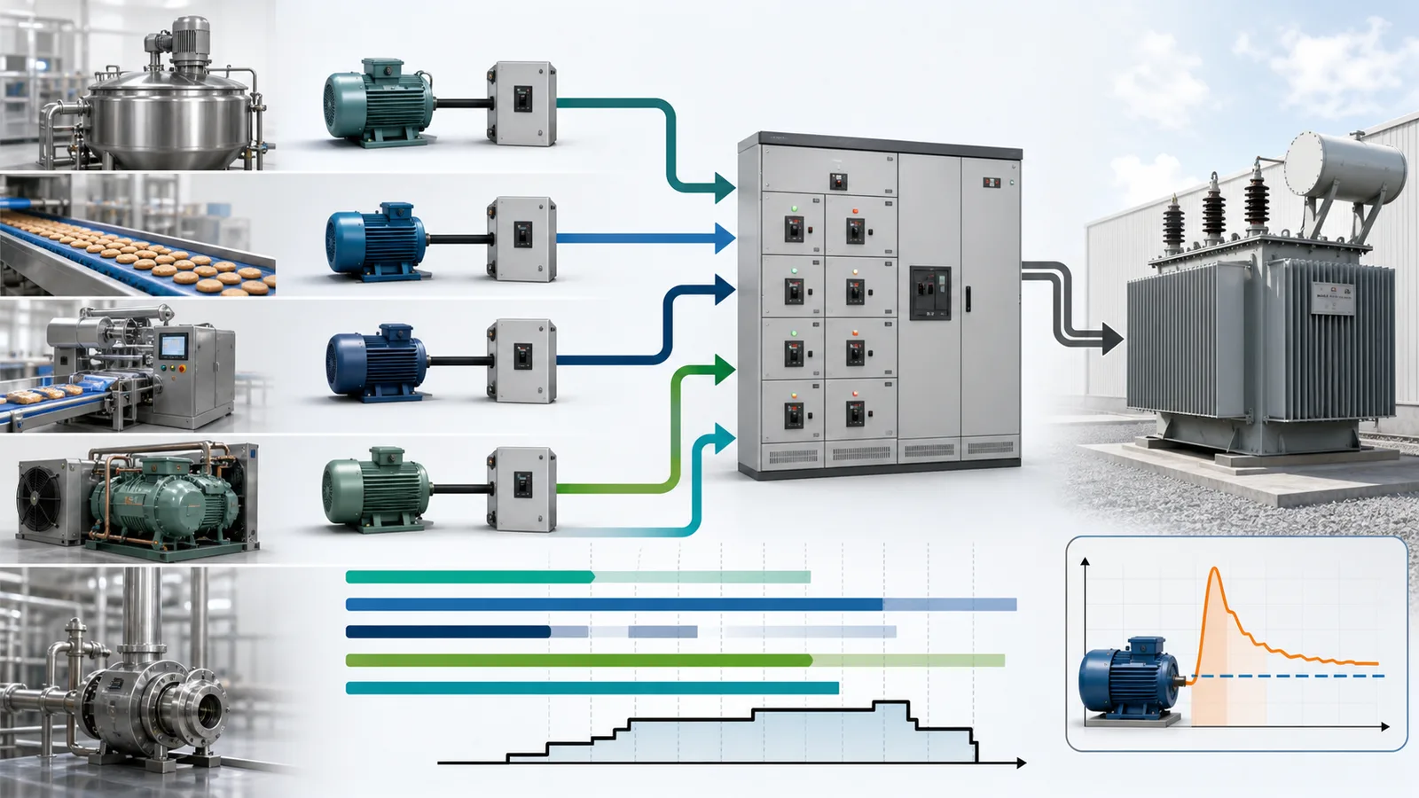
Calculate several operating scenarios
Normal production
Stable equipment operation with typical refrigeration, compressed air, packaging and occupied-area services.
Startup and recovery
Motor acceleration, heaters, compressors and line restart may overlap differently from steady production.
Cleaning and sanitation
Production may stop while pumps, hot-water systems, ventilation, pressure washers or CIP systems operate.
Defrost and pull-down
Cold stores and process refrigeration can create distinct peaks during pull-down, defrost or post-cleaning recovery.
Maintenance and test
Service outlets, lifting equipment, welding or test operation need an explicit basis instead of disappearing from the schedule.
Emergency and essential load
Define which controls, alarms, lighting, refrigeration or safe-shutdown functions require safety or standby supply.
Build a load schedule that engineers can use
Record country, voltage, frequency, phases, earthing arrangement and utility constraints.
Include process machines, thermal systems, refrigeration, air, water, HVAC, lighting, hygiene and support loads.
Separate motor output from input and request rated current, power factor, efficiency, starting method, duty and short-circuit data.
Use production, cleaning, startup, defrost, maintenance and emergency timelines.
Apply documented utilization and coincidence values by equipment or logical load group.
Evaluate kVA, current, phase distribution, power factor, harmonic-producing loads and transient behavior.
Identify known future equipment and reserve separately; do not hide uncertainty inside an unexplained percentage.
Qualified engineers select supplies, transformers, generators, switchboards, protection, cables, earthing and verification tests.

Motor starting, drives and power quality
Starting current and voltage dip
Direct-on-line motors, loaded starts and simultaneous restart can impose a short demand far above steady operation. Confirm motor and driven-load starting data.
Variable-frequency drives
VFDs change starting behavior and control but introduce drive-specific harmonics, leakage, EMC and protection considerations.
Power factor
Low power factor raises kVA and current for the same real kW. Correction equipment must be coordinated with harmonics and operating states.
Nonlinear and single-phase loads
Power supplies, controls, LED lighting and drives can distort current or load the neutral. Balance phases and assess harmonic effects.
The environment affects electrical design
Wet cleaning, condensation, flour or seasoning dust, fat, salt, heat, cold rooms, chemicals and frequent sanitation affect enclosure selection, cable routing, connectors, isolation, access and maintenance. The hygiene plan must not encourage unsafe washing of equipment beyond its declared protection or cleaning method.
What this calculator cannot select
A preliminary demand estimate cannot determine transformer size, generator size, switchboard rating, cable ampacity, protective devices, short-circuit withstand, selectivity, arc-flash controls, earthing, residual-current protection, emergency systems or enclosure suitability. Those decisions require current standards, local law, utility data, installation conditions and qualified electrical design.
Electrical load planning FAQ
Is connected load the same as maximum demand?
No. Connected load sums declared ratings; maximum demand depends on actual utilization and simultaneous operation in a defined time case.
Can I select a transformer from the calculator result?
No. The result is an input to transformer selection. The engineer must assess kVA, starting, harmonics, ambient and altitude derating, redundancy, expansion, protection and utility requirements.
Should every machine use the same utilization factor?
No. A continuously loaded refrigeration compressor, intermittent conveyor and batch mixer have different duty profiles.
Does a VFD remove motor-starting concerns?
It can reduce or control starting current, but the specific drive, motor, load, bypass arrangement, harmonics, EMC and restart logic still require review.
What data should a machinery supplier provide?
At minimum request supply voltage and frequency, phases, rated input or current, connected load, largest motor, starting method, power factor or drive data, duty, protection interface and environmental requirements.
Build the first electrical load register
Separate connected power, utilization and simultaneity before discussing plant supply capacity with the electrical designer.
Open Electrical Load EstimatorSources and technical references
- IEC 60364-1:2025 - current fundamental principles and safety requirements for low-voltage electrical installations.
- IEC 60204-1:2016+A1:2021 - valid consolidated requirements for electrical equipment of machines and coordinated machine groups.
- Electrical Installation Guide: Power loading - installed load, utilization, diversity and maximum-demand framework.
- Electrical Installation Guide: Installed apparent power - relationships among output power, efficiency, power factor, kVA and current.
- IEC 61439-1:2020/COR2:2023 - current general-rules reference for low-voltage switchgear and controlgear assemblies.
- NFPA 70, National Electrical Code - jurisdiction-specific U.S. installation requirements; verify the adopted edition and local amendments.